Hello, i want to test the output of the controller as you can see in the links bellow.
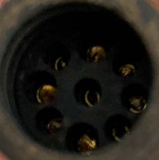
It got 8 outer pins and inner central pin.
In the 8 pin connection as shown bellow i have three large pins and 5 small.
i also have the multimeter shown bellow.
My plan is to plug in the battery turn on the byke and carefully test the output of the controller.
How should i program my multimeter so it will measure the signal correcty?
What is the logic behind these pins( i know that there is three phases and sensors)
What is the correct stratery to test the pins of the controller output?
Thanks.

 ibb.co
 ibb.co

It got 8 outer pins and inner central pin.
In the 8 pin connection as shown bellow i have three large pins and 5 small.
i also have the multimeter shown bellow.
My plan is to plug in the battery turn on the byke and carefully test the output of the controller.
How should i program my multimeter so it will measure the signal correcty?
What is the logic behind these pins( i know that there is three phases and sensors)
What is the correct stratery to test the pins of the controller output?
Thanks.
Whats-App-Image-2023-01-24-at-17-35-27 hosted at ImgBB
Image Whats-App-Image-2023-01-24-at-17-35-27 hosted in ImgBB
ibb.co
Whats-App-Image-2023-01-24-at-17-35-57 hosted at ImgBB
Image Whats-App-Image-2023-01-24-at-17-35-57 hosted in ImgBB
ibb.co