Err 30 - How to replace ESC Controller?

TrimmCreateBuilder

New member
Local time
11:41 AM
Joined
Feb 15, 2023
Messages
13
Hello,
I have a China bought E-bike. It's a fat tire style commuter.

Specs:
750 W
Bafang Motor
C901 Display

Problem:
As I turn on the system the display flashes the system is on and then within 1 second it goes to Err 30.

I have a similiar model e-bike and plugged in the working ESC controller and everythig works fine except the display LED modules.
I have traced it down to the Display giving a err 30 when I plug in the ESC controller that works.
Hub motor works, lights work, Pretty sure Pedal assist works.

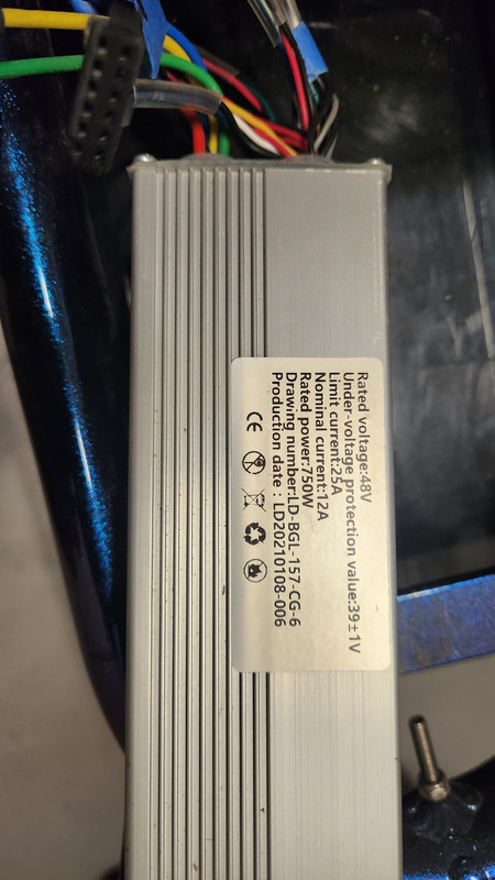
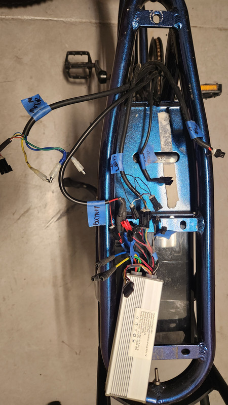
Attached are a few pictures of the labeled wiring and the ESC controller.

I am looking for help in replacing the controller.

I found one and not sure it' works.... ebay rep said its not compatible.


Any help or suggestions is greatly apprecaited.


20230208-162049.jpg
20230208-162033.jpg

20230208-162022.jpg
20230211-170954.jpg
 
My opinion, go with the 30A KT controller if the dimensions work for where the previous 25A one was (usually 30A controllers are larger), and buy a genuine KT display of your choice. The current C961 seems to be a Bafang or clone display and likely not compatible with a KT controller. With a genuine KT controller, and genuine display you know there will be no compatibility issues.

For what it's worth I have the color KT LCD8H display and find it good. Much easier to program than the cheaper black and white LCD3. All the programming parameters are on the one screen, rather than having to flick through to a different screen for each parameter.

I went through virtually the exact same exercise as you. Out of the crate the bike didn't work with I believe was the same message. Electrical connections were cheap, etc, etc. So after a LOT of stuffing around basically I just rewired the whole thing with a new larger amp controller, new display, quality electrical connections everywhere, and it now works perfectly.
 
Just noticed, for the 30A controller you are considering, just about every picture of it has different phase wire connections. In one picture the controller is described as having a waterproof connector and SM connections (that's what I'd expect). A single 9? pin waterproof connector for the phase and hall wires, and SM type connectors for everything else. You current controller is all individual wires.

So no major problem, but you may want to clarify exactly what type of phase and hall wire connections it has. If it does have the now near universal 9 pin waterproof type, you would need to buy a 9 pin type cable, and modifying it by cutting the 'other' end off, stripping the insulation back to make a short adaptor cable. If the controller comes with all individual wires no problem, but you're still likely to have to fit matching connectors. Don't scrimp on buying a good crimp tool to do that job. Any SM type connection that need to be made require a special SM crimp tool just for that job. You may need to learn how to swap pins around in an SM type connector. Things like your pas may have a different wiring scheme to the new controller. There is no universal wiring standard for these Chinese bikes.
 
Hey Freddy1, Thanks good input again. I have a store very close by that is called MarVac and I can get anything there. Like a Fry's for electronic cable, crimping tools and soldering and more. Either way, thanks for the input, I am very good and cable/ wire stripping, crimping and using all av tools. I just find the ESC controllers kind of difficult to diagonse why these china bikes used the parts they used. :( Dog SMH

I am looking at these here:


or


Links to eBay may include affiliate code. If you click on an eBay link and make a purchase, this forum may earn a small commission.
Good luck with sorting it all out.
Just stress again, if you need to crimp SM connectors it is an absolute must to have a different crimp tool to the 'regular' ratchet type. They are designed specifically for these tiny connectors. The point I'm getting to, the correct 'mini' SM crimp tools can be hard to find in general electronics stores. The ones they had in that type of store where I live did a crap job. With the correct tool it does it 100% perfect every time. I had to source mine online.
 
Hey ya Freddy! I got a Controller. Here is the photo of it all half way attached.

I have the marking in "Yellow" with a question mark cuase I am not sure what to do where to go with those.

The bottom of the photo there is a label "Light" in blue and a yellow question mark. not sure where that will go.

Also the 2 Red/blue wiring comes from the Controller....but the identifier is labeling them 'yellow/black' not sure if it's the same but i assume so. Would i connect 1 of those to where I have the "Display" labled? There is 1 2-pronger that would fit....but seems odd and I am not sure.

Looks I can get a new Motor Wiring cable to fit the HALL pass and phases....

PAS controller has a male.... and My Wiring from the PAS also has a "Male" I need to re-wire one or the other.

Throttle seems to be ok

Power I need to rewire as well.... looks like the guage of wiring is smaller from the battery to the end connectors.

what do you think here.... ? I think I am on the right track... but need to buy a few things.

Hope your into the help:) Thanks again.


ebike_Wiring_purplePOS.jpg
 
It's hard to give the right answer from the photos not knowing where the wires on your bike are coming from. Some are obvious such as the battery connections. You're simply going to have to get a set of matching connectors to the new controller, cut the old ones on your bike off, and crimp on the new connectors using a quality crimp tool. If the tool isn't a ratchet type, it isn't a quality tool.
Rather than tell you what each connector is called, here's a link that should tell you all you need to know about connector types .... Connector Types

The best advice I can get is the methodology I use to sort this sort of stuff out. Go source a cheap container full of smallest size multi colored cable ties. I use these as connection guides. You know what each of the controller outputs do from the documentation. So put a different coloured cable tie just behind the connector, like a collar, cutting it neat. Write down somewhere what function each color represents. Then work through each of the bikes old cables tracking it back if necessary to where it comes from to identify its function. Reading from your document, put the appropriate matching coloured cable tie just behind the bikes existing connection.
Now you have a pile of coloured connections coming from the controller, a pile of coloured connections coming from the bike. So now its just a matter of either plugging them in (if the connects and wiring scheme match), or changing the bikes old connector to match the one on the controller.
Any 'unused' connections from the bike cabling just need to be investigate as to what they actually do, and if necessary dealt with on a case by case basis. My bike is pretty straight forward and only has bike cabling that's identical to output leads from the controller. It has no 'tricky' stuff so others would have to assist if there are necessary 'extra' connections on the bike stopping it from working.

P.S. be sure to check the color of wires match between the two halves of the connectors. Moving them if they don't is fiddly, but not really that hard once the technique of slipping the pin out of the connector is figured.
 
@Freddy1 well sir, it's got the same err 30 message. I hooked up the entire system and i still can't get the er 30 to go away with the new Controller.

Man.... I don't know what I did wrong.


Here is a video to share with you maybe you can help analyze again?

https://photos.app.goo.gl/QVgegY2C1oRTtcvA9


Is it possible I could burn or ruin the contoller? Should I just buy the entire wiring system and start all over?

Thanks man.
 
Given the problems you are having, buy a new genuine display. A black and white LCD3 is cheap, and then completely rewire everything.

That doesn't mean new wire for things like throttle, pas, etc. With that done the only thing remaining is the motor. So test that with a multimeter and by connecting two phase wires together that you experience 'chugging' when you turn the wheel backward by hand.

It would take me to long to type how to test a motor as there is already good explanations online. All you need is a dirt cheap multimeter.
 
Back
Top